Table of Contents
Hall Effect
The Hall Effect occurs when an electrical charge passing through an electrical conductor produces an asymmetric distribution of charge resulting in a voltage difference and a magnetic field perpendicular to the current.
The Hall Effect Sensor is a device that reacts to the magnetic field of a magnet and outputs a charge proportional to the distance of the magnet.
Very clear and thorough explanation by Professor Bowley of University of Nottingham:
Summary
Introduction
To illustrate the way electrons behave as they travel through a conductor, let us look for a parallel example. The directional property of the flow of electrons though a conductor more closely resembles the flow of a hiker along a trail than water through a pipe. The trail is the path of least resistance, yet if subjected to an external force (say, for instance, the presence of a bear and cub) the hiker will veer to the opposite side of the trail. This is to say that the flow of electrons in a conductor may be directly influenced by forces outside of the conduit.
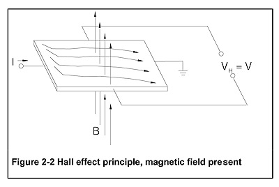
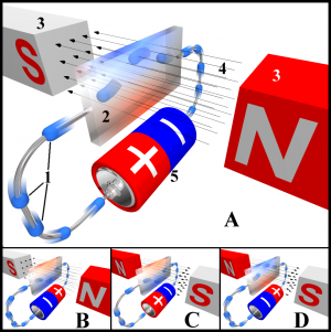
Closely linked to electric current is magnetism. Any electric current generates a magnetic field, and as was demonstrated by Michael Faraday, any magnetic field generates an electric current. In a conductor with an established current flow, the presence of a magnetic field will cause a deflection of current in which the potential of one transverse side of the conductor will have a higher potential than the other. This is what is known as the Hall Effect.
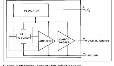
A simple hall effect sensor is comprised of two separate circuits:
- The bias circuit which applies a fixed voltage to the “top” and “bottom” terminals of the semiconductor material
- The measurement circuit which senses a voltage between one “side” of the semiconductor material to another.
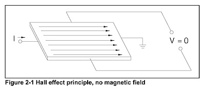
In the absence of a magnetic field the measured voltage is insignificant, but when a magnetic field is applied either “into” or “out of” the semiconductor material, a voltage is induced across the width of the material. The hall voltage is directly proportional to the strength of the magnetic field. Note that the field strength, and thus the voltage, is not linearly related to the distance between the sensor and the source of the magnetic field (i.e. the magnet). The pole orientation of the magnet (either north or south polarity) with respect to the sensor, determines if the magnetic field lines are directed “into” or “out from” the sensor.
Types of hall effect sensors
Hall Effect sensors come in two basic types:
- Threshold (alternatively called digital, or on-off), which produce a constant hall voltage when the field strength reaches a certain amplitude and/or polarity. There are many different threshold device configurations such as latching devices which turn on when a positive field strength reaches the threshold but only turn off under a negative field of the same strength, or devices which turn on when only a positive field reaches a certain threshold and are off otherwise, or devices which turn on when either a positive or negative field reaches the threshold and are off otherwise, etc. Certain devices even have programmable thresholds.
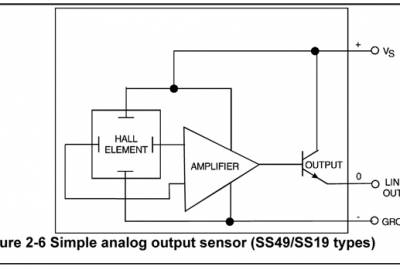
- Linear, (analog output sensor) which produced a hall voltage proportional to the strength of the magnetic field around it. The orientation of the surrounding magnetic field determines the polarity of the voltage swing. Linear devices are more often used in musical applications, when expressive gestures must be sensed as tiny changes in position.
Usage
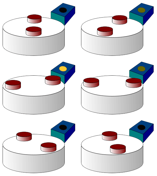
Hall sensors are commonly used to time the speed of wheels and shafts, such as for internal combustion engine ignition timing or tachometers. In the pictured wheel carrying two equally spaced magnets, the voltage from the sensor will peak twice for each revolution. This arrangement is commonly used to regulate the speed of diskette drives. It was also employed to measure speed of rotation in Elliot Sinyor's Gyrotyre, in a configuration similar to that shown below.
Threshold devices can be used as proximity switches, or as counters. Several can be used together to do timing analysis or very coarse positional measurements.
Linear devices can measure field strength which varies with position (and thus speed and acceleration) though not linearly. Curve fitting techniques can be applied to give a linear relationship between output voltage and magnet distance. Linear devices and also be used as tilt sensors as the magnetic field strength varies with the projection in the transverse axis. Two or three-axis devices exist, allowing measurements to be done in more degrees of freedom.
Features
- fast operation
- long life
- highly repeatable
- no moving parts
- broad temperature range
- inexpensive
Issues
- short range -sensing gap
An application for this sensor used in the context of musical instruments is the Hyper Flute by Cleo Palacio Quentin. There are two hall sensors used on the G# and C# levers of the flute. The small range of the keys are measured in ninety five steps giving the performer very precise control over the parameters she is controlling.
Explanation and performance by the artist on Interfaces Montreal (in French): http://www.interfacesmontreal.org/en/videos/hyper-flutefrom-instrumental-gestureto-digital-processing
Devices
| Everlight HI300/D1 | |
|---|---|
| Sources | PartMiner |
| Description | Description: Threshold hall effect sensor |
| Datasheet | hall_effect.pdf |
| Resources | |
| Notes | |
| Variants | |
Media
External links and references
- “The Hall Effect”. nist.gov.
- Hall, Edwin, “On a New Action of the Magnet on Electric Currents”. American Journal of Mathematics vol 2 1879.
- Fraden, Jacob. 2001 Handbook of Modern Sensors: Physics, Designs, and Applications. Springer Verlag.
- Miranda, E. R. and Wanderley, M. M. 2006. New Digital Musical Instruments: Control And Interaction Beyond the Keyboard. A-R Editions.
- Pallás-Areny, E., Webster, John. 2000 Sensors and Signal Conditioning, 2nd Edition
