Table of Contents
Ultrasound
Summary
Ultrasonic sensors are based on measuring the properties of sound waves with frequency above the human audible range. They are based on three physical principles: time of flight, the Doppler effect, and the attenuation of sound waves. Ultrasonic sensors are non-intrusive in that they do not require physical contact with their target, and can detect certain clear or shiny targets otherwise obscured to some vision-based sensors. On the other hand, their measurements are very sensitive to temperature and to the angle of the target.
Introduction
Ultrasonic sensors “are based on the measurement of the properties of acoustic waves with frequencies above the human audible range,” often at roughly 40 kHz 1). They typically operate by generating a high-frequency pulse of sound, and then receiving and evaluating the properties of the echo pulse.
Three different properties of the received echo pulse may be evaluated, for different sensing purposes. They are:
- Time of flight (for sensing distance)
- Doppler shift (for sensing velocity)
- Amplitude attenuation (for sensing distance, directionality, or attenuation coefficient)
Modes of Operation
1. Time of Flight
1A. Reflection Mode
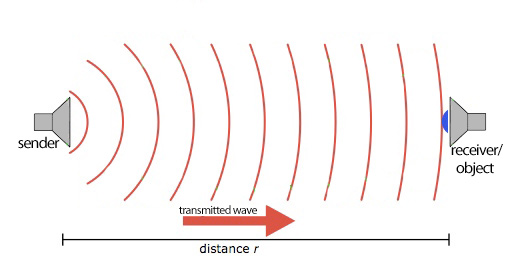
In reflection mode (also known as “echo ranging”), an ultrasonic transmitter emits a short burst of sound in a particular direction. The pulse bounces off a target and returns to the receiver after a time interval t. The receiver records the length of this time interval, and calculates the distance travelled r based on the speed of sound c:
r = c * t2)
Very often, separate transmitting and receiving transducers are placed immediately next to each other, housed as a single unit. (The PING))) Range Finder, Omega flowmeter and Migatron high-accuracy sensor below are all designed this way.) In these cases, the distance calculated will be twice the distance from the sensor to the target.
Using proper coordination, a single transducer can be used for both emitting the pulse and receiving the echo. Note that it takes time for the transducer to change modes, presenting a challenge to short-distance measurement.
1B. Direct Measurement Mode
In this mode of operation the transmitter and receiver are two separate units that move relative to each other. For example, the receiver can be fixed to a target that moves relative to a stationary transmitter, or vice-versa.
Multiple transmitters can be used to increase the directionality of the transmitted pulse. Lima et al.3) placed multiple ultrasonic transmitters on a performer, whose signals were received by multiple receivers in the performance space, enabling a computer program to triangulate the performer's position.
Doppler Shift
When a wave reflects off of a moving object, its frequency is shifted by an amount proportional to the velocity of the object. This fact can be exploited in ultrasonic sensing by having the receiver measure not the time of flight but the frequency of the returning echo pulse. Knowing fe and fr, the frequency of the emitted and received pulse, respectively, the velocity v of the target may be calculated:
fe - fr = 2 fe (v / c) cos(A)4)
where A is the angle between the target's and the pulse's lines of motion.
Amplitude Attenuation
Ultrasonic sound attenuates much faster than audible sound when propagating through air. By measuring the intensity of the returning pulse, an estimate of the distance travelled can be made using the following equation:
I = I0e-ax 5)
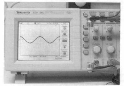
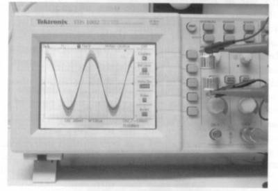
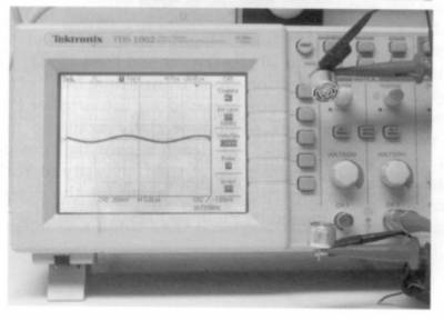
where I and I0 are the received and the original intensities, respectively, and where a is the attenuation coefficient (a property of the medium) and x is the distance travelled by the wave. Attenuation may also be caused by an increased angle between the target and receiver, which may even deflect the echo somewhere else and not be heard at all. The effect of distance and angle on the amplitude of the received signal is illustrated in the following images from (Miranda & Wanderley 2006).6)
Making Measurements
The three methods above make use of different physical principles, but they all employ the same measuring procedure. In each case, an ultrasonic sound wave is created, received, and evaluted.
Generating the ultrasonic signal
Ultrasound is most commonly generated as a direct conversion from electrical energy. This is accomplished by applying a rapidly oscillating electrical signal to a piezoelectric crystal attached to a mounting. The charge causes the crystal to expand and contract with the voltage, thereby generating an acoustic wave. The waves are later detected by a piezoelectric receiver, which converts the waves back into voltage using the same method.
The signal may also be generated by consumer electronics products, but great care must be taken to ensure that the signal is not attenuated in this range. Speakers typically have filter circuits to prevent ultrasonic propogation, and the frequency response of many microphones roll off in this range. This is partly because of the amount of ultrasound present in our daily life; percussive sounds and metallic ringing both contain ultrasounic frequencies.
Pulsed vs. continuous measurement
Time-of-flight-based sensing requires emitting a pulse and waiting for it to return. This waiting time limits the speed with which successive measurements can be made, without risking confusion. However, Doppler- and attenuation-based sensing devices do not have the same restrictions: a constant wave of ultrasound may be emitted, and the received wave's attenuation or frequency continuously analyzed. This may make measurements speedier, effectively increasing the sensitivity of the sensor.
Considerations
The main advantage of ultrasonic sensors is that measurements may be made without touching or otherwise impeding the target. In addition, depending on the distance measured, measurement is relatively quick (it takes roughly 6ms for sound to travel 1m). However, many factors such as temperature, angle, and material may affect measurements.
Here is a list of pitfalls in ultrasonic sensing:
- Weather. Temperature and humidity affect the speed of sound in air. Therefore, range finders may need to be recalibrated to make accurate measurements in a new environment. (Or, an on-board temperature sensor may be incorporated.)
- Currents. Temperature variations and air currents can create invisible boundaries that will reflect ultrasonic waves, so care must be taken to avoid these.
- Angle. For the transmitted wave to echo back to the receiver, the target surface must be perpendicular to the transmitter. Round objects are therefore most easily sensed since they always show some perpendicular face. When targeting a flat object, care must be taken to ensure that its angle with respect to the sensor does not exceed a particular range.
- Dead-zone. Ultrasonic sensors typically have a “dead zone” immediately in front of them in which objects cannot be detected because they deflect the wave back before the receiver is operational. (This is because reverberations from the transmitter force the receiver to pause a moment before beginning to listen for the echo.7))
- Material. Some materials are more absorbent than others, and these will reflect less ultrasound. This complicates using the attenuation method to measure the distance of arbitrary objects.
Devices
| Jameco Electronics 40TR16F-R | |
|---|---|
| Sources | Jameco US$ 7.95 |
| Description | Ultrasonic sensor transmitter/receiver pair, used for motion or distance sensing |
| Datasheet | 40TR16F-R |
| Resources | Jameco product page |
| Notes | |
Transmitter sound pressure level: 119dB
Receiver sound sensitivity: 65dB |
| Parallax Inc. PING))) Ultrasonic Distance Sensor (#28015) | |
|---|---|
| Sources | |
HVW Technologies US$ 29.99
Lynxmotion
US$ $27.95 |
| Description | Ultrasonic range finder, single transmitter/receiver unit |
| Datasheet | 28015-PING-v1.5.pdf.pdf |
| Resources | Using PING))) with Arduino |
| Notes |
Maximum echo pulsewidth: 18.5ms (minimum number of measurements per second roughly 50)
Range: 2cm-3m |
| Variants |
| Omega FD-400 | |
|---|---|
| Sources | Omega US$ 1695.00 |
| Description | Doppler flowmeter |
| Datasheet | FD-400 series |
| Resources | User manual |
| Notes | |
Liquid must contain “100 ppm of useful sonic-suspended reflectors greater than 100 microns.”
1-60 second response time |
| Variants | FD-400 series products range from $1696 to $2185, with variations in output power. |
| Migatron Corp. RPS-412A | |
|---|---|
| Sources | Migatron price not listed |
| Description | High accuracy distance sensor |
| Datasheet | RPS-412a |
| Resources | User manual |
| Notes | |
Built-in temperature sensor automatically compensates (50 times per second) for changes in speed of sound due to environmental effects
Sturdy stainless steel housing
Input voltage 20-30 V; output signal 0-10 V.
NB: Company product page has many broken links |
| Variants |
Media
External Links & References
Resources
- Massa, D. 1999. Choosing an ultrasonic sensor for proximity or distance measurement. Sensorsmag. 1 February.
- Ultrasound Technology Information Portal. http://www.us-tip.com/serv1.php
- Wilson, J. 2005. Sensor Technology Handbook. Oxford, UK.: Elsevier.
- Pallàs-Areny, R., and J. Webster. 2001. Sensors and Signal Conditioning, 2nd ed. Toronto, Ontario: John Wiley & Sons.
- Joseph J. Carr. 1993. Sensors and Circuits. Upper Saddle River, NJ: PTR Prentice-Hall, Inc.
Applications
- Audio Spotlight. Holosonics
- Marshall, Mark. The T-Box. Project description.
- Raes, Godfried-Willem, 1999/2004. Gesture Controlled Musical Instruments - A Practical Report
- Taxonomy of Realtime Interfaces for Electronic Music Performance. Tag: ultrasound
- Vogt, F. et al. 2002. Tongue 'n' groove: An ultrasound based music controller. Proceedings of the 2002 Conference on New Instruments for Musical Expression. PDF
- Some industrial applications link

