This is an old revision of the document!
Table of Contents
Servo Motors
Servomotors allow for easily controlled rotation using either a rotational or linear actuator. While often more expensive than other types of rotational motors, such as stepper motors, they contain feedback mechanisms that allow them to measure their own angular position, with some more expensive models also tracking their angular speed. These systems can help reduce overshoot and increase angular accuracy, while also allowing them to be position-aware upon their power on, without the need for a self-calibration routine.
Construction
A servomotor generally consists of a control circuit attached to a small motor with a low amount of magnetic poles (resulting in a high rotational speed and low torque) which is then attached to a series of gears. These gears slow down the rotations but increase the torque of systems, allowing for the system to have a constant level of torque at all rotational speeds. A feedback system, such as a potentiometer, is then attached to the final gear. This feedback is then used to adjust the control signal as needed. For example, if overshoot is detected an H-Bridge could be implemented to invert the voltage and thus the rotational direction of the motor.
Operation types
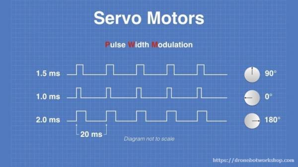
These motors are generally grouped into two sets of operations, either continuous or positional, based on how they respond to a PWM signal. A continuous motor will have its rotational speed determined by the pulse width of the signal and will continue to rotate along its axis as long as it’s powered.
A positional motor will rotate to a specific angle within its rotational range and stay there as long as the pulse width is constant. This rotational range is frequently 180°, but maybe more or less depending on the unit.
The PWM signal needed to control a servo motor can be easily produced by a microprocessor, but the timing of these pulses can be quite computational taxing, especially for smaller chips when multiple motors or sensors are involved, so an external controller board, such as the PCA9685, may be used.
Specifications
There are a handful of specifications provided by most manufacturers that can help you select the right servo motor for your project. This includes Motor Size, Gear Material, Speed, Torque & Operating Voltage.
Motor Size
The Motor Size is may be provided in inches or metric units, or a more general standardized size. These sizes are Nano, Sub-Micro, Micro, Mini, Standard, Large.
Gear Material
Gear material provides information on what the internal gears are constructed from, often either metal or plastic. Metal gears are more durable, and provide higher torque and speed, but also add additional cost and weight to a system.
Speed
Speed refers to how quickly the motor can rotate 60°, often notated in the unit sec/60°
Torque
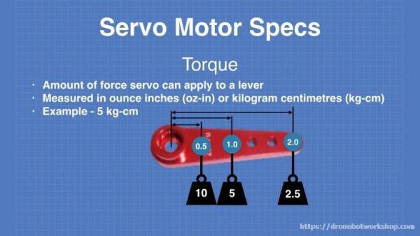
Torque provides information on the force applied by the motor, provided in kg/cm or oz/in. This represents the weight that can be held on a lever at that much distance from the shaft, with each doubling of distance resulting in a halving of the supported weight.
Operational Voltage
Operational voltage provides the number of volts that must be supplied to a motor for it to operate at its maximum performance.
Frequent applications of servomotors are robotics, such as robotic arms, where rotational accuracy is valued. This also makes servo motors a good fit for applications such as CNC machines, 3D printers, and other automated manufacturing.
This built-in feedback system can also be used to measure rotations, such as its use in the vBow, where it is used to measure bow speed, angle, and placement on the instrument. As mentioned above, the gear system used in a servo motor allows for a constant level of torque at all it’s rotation speeds, which may be desirable.


