Table of Contents
Force-sensitive Resistor (FSR)
Summary
Introduction
A force-sensitive resistor (alternatively called a force-sensing resistor or simply an FSR) has a variable resistance as a function of applied pressure. In this sense, the term “force-sensitive” is misleading – a more appropriate one would be “pressure-sensitive”, since the sensor's output is dependent on the area on the sensor's surface to which force is applied. Commercially fabricated FSRs are often made with fixed shapes and sizes, but offer reliable outputs and are relatively inexpensive.
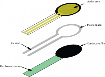
These devices are fabricated with elastic material in four layers, consisting of:
- A layer of electrically insulating plastic;
- An active area consisting of a pattern of conductors, which is connected to the leads on the tail to be charged with an electrical voltage;
- A plastic spacer, which includes an opening aligned with the active area, as well as an air vent through the tail;
- A flexible substrate coated with a thick polymer conductive film, aligned with the active area. This polymer is very often replaced by a layer of FSR ink.
When external force is applied to the sensor, the resistive element is deformed against the substrate. Air from the spacer opening is pushed through the air vent in the tail, and the conductive material on the substrate comes into contact with parts of the active area. The more of the active area that touches the conductive element, the lower the resistance. All FSRs exhibit a “switchlike response”, meaning some amount of force is necessary to break the sensor's resistance at rest (approximately 1 MΩ), and push it into the measurement range (beginning at approximately 100 KΩ) (Interlink Electronics 2005).
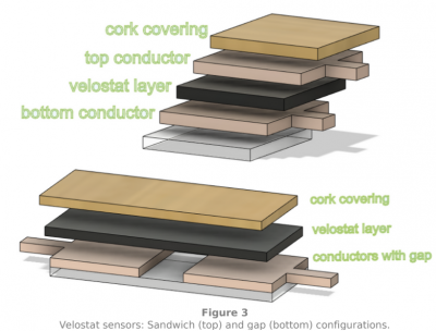
There are several options for creating custom FSR shapes and configurations using pressure-resistive conductive materials such as conductive rubber, paper, and ink, or Velostat. These flexible materials can be cut, shaped and stacked to better fit designs and resistance characteristics needed in a design. The pressure-resistive materials alone don't operate as sensors though, and must be configured with conductors to extract resistance changes from the material.
Utilizing the same voltage divider concept in commercial FSRs, both configurations should attach an additional fixed resistor in series with the sensor to avoid short circuits. The sandwich configuration shown above can also be extended to detect touch position by separating the bottom conductor into different shapes. With each conductive piece receiving its own voltage difference, relative touch position can be determined.
Operationally, an FSR is very similar to a strain gauge, the main difference being that a strain gauge's backing deforms with the resistive element, while an FSR's does not. This fact is important to consider when mounting an FSR against a support, as discussed below.
The same applied force will result in a wider output swing in a FSR than a strain gauge. Strain gauges, however, have higher accuracy than an FSR. Depending upon the particular needs of the application, one may choose one or the other. Ultimately, a major consideration in the choice of a sensor is cost; a major advantage of FSRs is their low cost.
Using an FSR
One of the most common circuits implemented to utilize an FSR's output is the voltage divider. A voltage (usually +5 V) is applied to one of the sensor's leads, while the other is attached to a second resistor with fixed value. The other end of the fixed resistor is grounded, dividing the voltage and preventing a short circuit when the FSR's resistance drops to 0. In this way the FSR is able to measure the “voltage drop across a resistor”. The resistance value of the second resistor determines the output range of the sensor. Typically, 100 KΩ will yield a sensor output suitable for common ADCs used for musical applications. FSRs are not polar, meaning it does not matter which side receives the voltage.
Mounting
Because the FSR's operation is dependent on its deformation, it works best when affixed to a support that is firm, flat, and smooth (Burdea 1994). Mounting to a curved surface (as is often the case when placing sensors on the body or clothing, especially on a dataglove) reduces measurement range and resistance drift. One solution is to use a sensor with a smaller active area, since less of the sensing area will be deformed by the contours of the body. Bending the tail will also affect performance because the air vent will be deformed. In cases where bending the sensor cannot be avoided, a preliminary calibration is strictly necessary to assure consistent results. Moreover the tail is also relatively fragile, and if bent far enough the conductive leads inside it will break, rendering the sensor useless and difficult to repair.
Output
The FSR's output signal is a monotonic function of area and pressure. When enough force is applied,this function changes slope quickly due to sensor saturation. After this point output will not be significantly affected by an increase in applied pressure.
This sensor is known to have poor accuracy, with errors up to 25% of output (Burdea 1994) but can be a good choice if only qualitative measurements are needed.
History
The FSR was invented by Franklin Eventoff in 1977 as an attempt to make digital instruments more expressive. Early instruments include the Sonica and Mattel's Magical Musical Thing. In 1985 Eventoff founder and CEO of Interlink Electronics. He has left interlink and has started a new company called Sensitronics.
Devices
Prices listed below are updated to March 2011
Interlink Electronics FSR
Description: Force Sensing Resistors
Datasheet: FSR Integration Guide and Evaluation Parts Catalog
Resources: nice spec summary from Robotshop
Notes: Prices vary depending on the size and shape of the sensor. See also the “FSR Design Kit.”
Variants: There are four formats: 0.2“ and 0.5” diameter circular, 1.5“ x 1.5” square, and 24“ long strip
Interlink Electronics FSR Design Kit
Sources
- Interlink Electronics US$100
- Robotshop CAN$140.26
Description: Contains 4 FSRs of each of the four models: Model 400, 402, 406 and 408 sensors, as well as overlays and adhesives, FSR Integration Guide, Evaluation Parts Catalogue, Technical Notes and Suggested Interface.
Datasheet: FSR Integration Guide and Evaluation Parts Catalog
Resources: nice spec summary from Robotshop
Notes: Great kit for beginners, except for the waste from the limited range of sizes available!
Variants:
Tekscan FlexiForce sensors
Sources
- Tekscan US$99 for the starter kit.
Description: FlexiForce sensors family. Resistive Force Sensor
Datasheet: Flexiforce User Manual
Resources:
Notes:
Variants: A201 MODEL; HT201 (HIGH-TEMP) MODEL; A401 MODEL
Infusion Systems TouchMicro-5 v1.2
Sources
- Infusion Systems US$48.
Description: Zero-travel force sensitive resistors.
Datasheet: Product web Page
Resources:
Notes:
Variants: Lots of variants according to the size, length of the tail and smoothness of the response. All the members of the Touch family share the same technology. Price varies according to the size.
Sensitornics Force Sensing Resistors
Sources
- Sensitronics Unknown price
Description: "The Original Force Sensing Resistors"
Datasheet: Technical informations
Resources:
Notes:The Force-Sensing Resistor are available in both Shunt Mode and Thru Mode
Variants: Force-Sensing Resistor; Translucent FSR; Clear FSR
IEE, formerly LuSense
Sources
- IEE Unknown price
Description: Force Sensing Resistor (FSR)
Datasheet: N/A
Resources:
Notes:The information on the website of the company are very vague about the technical characteristics of the sensors. No datasheet is available.
Variants:
Velostat
Sources
- Adafruit US$4.95 per sheet
Description: 1mm flexible pressure-sensitive resistive material
Datasheet: N/A
Resources:
Notes: Material also known as Linqstat.
Variants:
Media
External links & references
- G. Burdea, Force and Touch Feedback for Virtual Reality. New York, NY: Wiley, 1996.
- Interlink Electronics, 2005, ”FSR Integration Guide & Evaluation Parts Catalog“, Company brochure, Camarillo, CA, 26 pp.
- Koehly, Rodolphe, et al. “In-house development of paper force sensors for musical applications.” Computer Music Journal 38.2 (2014): 22-35.


