Table of Contents
Linear Variable Differential Transformer (LVDT)
Introduction
 causes current of variable voltage to be induced from the current source (A) to the two secondary coils (B). From Wikipedia: LVDT")
A Linear variable differential transformer, or LVDT, is based on the principles of magnetic induction, the same principle of a “wall-wart” voltage transformer utilized in many electronic device designs. LVDTs have historically been a popular sensor for military and manufacturing applications (Nyce2004), partially due to their extremely high resolution but also due to their simplicity and robustness. They also have a high linearity, repeatability and accuracy (Wilson2005).
LVDTs have been described as “a passive inductive transducer” (Webster1999), “an accurate and reliable method for measuring distance” (Wilson2005) and “a type of electrical transformer used for measuring linear displacement” (Wikipedia).
History
The LVDT's original idea was proposed in a patent by George B. Hoadly titled “Telemetric System”, intended as “…a system for the electrical transmission of intelligence at a distance” (Hoadly1936). The original design had some structural and operational differences to its successors, but the fundamental technology of the sensor has not changed significantly since its invention (Nyce2004). In 1946, Herman Schaevitz published “The Linear Variable Differential Transformer”, a paper describing an LVDT design which is nearly identical to the LVDTs sold commercially to this day (Wilson2005). The primary differences between more modern versions of the sensor and their predecessors lay mainly in the areas of miniaturization and materials, allowing smaller and more accurate sensors to be made (Nyce2004). The use of the LVDT was historically dominated by the military until lowering costs lead to widespread use in a variety of industries (Nyce2004). LVDTs require few components and can be hand-constructed (Powell2009), although it is very difficult to match the quality of commercial units.
Construction
An LVDT is composed of seven components, not including the conditioning circuitry:
- Primary coil
- Secondary coil 1
- Secondary coil 2
- Ferromagnetic core
- Shaft
- Shield
- Handle
The ferromagnetic core is the moving component whose position within the shaft is sensed. Around the shaft are wound three inductors, the primary winding in the middle and the secondary windings (wound in opposite direction) on either side of the primary. Each of the secondaries should have the same number of turns and be of the same length, otherwise the null position and linearity will be affected. A cylindrical shield protects the windings from damage and also serves to contain the magnetic field used for sensing. The physical component which will be measured using the LVDT is mechanically coupled to the ferromagnetic core using a threaded (and non-ferromagnetic) handle. For some applications, a guide system and even a spring-return (which is known as a “gagehead” configuration) may be included in the assembly.
Signal Conditioning
The conditioning circuit for an LVDT is relatively complicated and plays an important part in the linearity and precision of the device (Nyce2004). Firstly, an oscillator excites the primary winding which is coupled with the secondary windings each to a degree dependent upon the position of the ferromagnetic core. If the core is in the centre position, then the secondaries will be equally coupled to the primary. If the core is displaced from its centre position, then one of the secondaries will be more strongly coupled and will echo the excitation signal to a greater degree.
One of the secondary windings, being wound in opposite direction to the other two inductors, will output the excitation signal in the opposite phase. This is used in order to obtain a differential voltage indicating the direction of the displacement: the outputs of the secondary windings are rectified and summed to produce a voltage that varies linearly between the +/- the maximum displacement with the centre position being at zero volts.
The simplest methods of demodulation involve some form of diode rectification, while more complex structures involve synchronous demodulation. In either case, the secondary coils' output is processed through low-pass filtering to remove AC components and leave a DC signal proportional to the displacement. When measuring absolute voltage values, one must account for offset errors and drifts and other measurement inaccuracies. Hence, nearly all LVDT circuitry today uses a ratiometric design (or “Sum of Secondary Feedback” method for non-uC circuits). It is a common and well-known technique for eliminating absolute errors using ratios between values. Ratiometric methods are applied to eliminate changes due to the excitation voltage shifts when measuring LVDT signals and compensates for any drifts or other LVDT construction inaccuracies. Such a process requires more complicated circuitry than a non-ratiometric design (e.g., synchronous detection) - but it provides significant benefits. Additionally, it is only valid if the core is kept sufficiently within both coils and the sum of secondary coils' signals remains relatively constant (Nyce2004). Nowadays, the difference in circuitry is not problematic due to the advances in IC design and microcontrollers.
A simplified ratiometric signal conditioning (Szczyrbak1997):
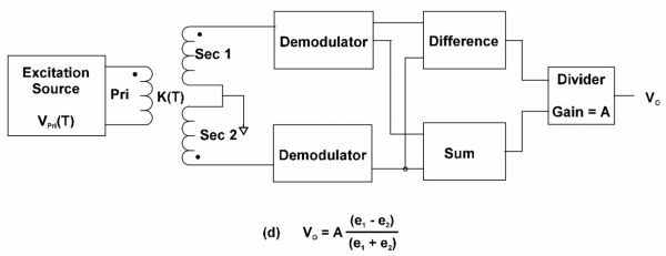
The above-simplified schematic requires 5-wire LVDT (as oppose to the 4-wire LVDT appropriate for the phase-sensitive demodulation). Both secondary coils' outputs are processed independently, through full-wave rectification and low-pass filtering (typically Fc of the Butterworth filter is x0.1 of the excitation frequency). The signals are processed in a ratiometric block (subtracted signals divided by the sum of both signals). The output is a DC voltage proportional to the core displacement.
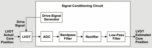
A fully digital approach can be applied as well, where the output of both coils is fed through ADC and processed further in the digital domain (Vemuri2017):
Below, a simplified mathematical simulation of the LVDT (MaxMSP) demodulation:
Signal Conditioning (Other)
Another interesting approach for demodulation consists of the low-cost elements and is based on the sample & hold circuitry instead of the traditional rectification and low-pass. Such an approach provides better speed performance (integration every half-cycle of excitation frequency) of the LVDT and reduces circuit complexity.

In (Petchmaneelumka2017) “(…) simple circuit technique to realize the LVDT signal to DC voltage converter is introduced. The technique is based on the ratio of sum and difference of the signals from two secondary windings. The proposed scheme comprises an operational amplifier (opamp) and operational transconductance amplifier (OTA) as an active circuit building block. The sum of two secondary winding signals is provided for the reference signal to generate the control signal for the SHC. The control signal for the SHC is obtained by the peak-amplitude finder (…)”. Other techniques introduced by the same author propose even simpler, yet effective, LVDT demodulation.
The time-series below illustrate the signal path progression, from primary coil excitation signal (V1) and voltage on the sum of secondary coils (Vd), through peak detection (Vc) to trigger sample&hold circuit, to the final output Vo proportional to the core displacement.

Devices
| MSI Inc. / Shaevitz MHR-500 | |
|---|---|
| Sources | |
Component Distributors, Inc CAN$ 599.00
|
| Description | ±12.7mm AC-operated LVDT |
| Datasheet | MHR_Series.pdf |
| Resources | |
| Notes | |
| Variants |
| MSI Inc. / Shaevitz GCD-121-500 | |
|---|---|
| Sources | Digikey CAN$ 955.00 |
| Description | ±12.7mm DC-operated spring-return (gagehead) LVDT |
| Datasheet | GCD_Series.pdf |
| Resources | |
| Notes | |
| Variants | |
External links & references
- (Nyce2004) David S Nyce, “Linear Position Sensors”. John Wiley & Sons, Hoboken, New Jersey, 2004.
- (Webster1999) John G Webster, “The Measurement, Instrumentation, and Sensors Handbook”. CRC Press with IEEE press, Boca Raton, Florida, 1999.
- (Wilson2005) John S Wilson, “Sensor Technology Handbook”. Elsevier, Burlington, Massachusetts, 2005.
- (Hoadley1936) George B Hoadley, “Telemetric System”. US Patent Application #2196809, March 17th 1936 (Patented on April 9th 1940).
- (Powell2009) Mike Powell, Mike’s Flight Deck
- (Szczyrbak1997) Szczyrbak, J. “LVDT Signal Conditioning Techniques”, 1997
- (Vemuri2017) Vemuri, A. & Torres, H. “Signal-to-noise ratio of an LVDT amplitude demodulator”, Analog Applications Journal, 2017
- (Petchmaneelumka2017) Petchmaneelumka, W., Songsuwankit, K. & Riewruja, V. “Simple LVDT Signal to DC Converter”, 2017
- RDP Group, 2002, LVDT principle of operation.