This is an old revision of the document!
Table of Contents
Linear Variable Differential Transformer (LVDT)
Introduction
A Linear variable differential transformer, or LVDT, is based on the principles of magnetic induction, the same principle of a “wall-wart” voltage transformer utilized in many electronic device designs. LVDTs have historically been a popular sensor for military and manufacturing applications (Nyce2004), partially due to their extremely high resolution but also due to their simplicity and robustness. They also have a high linearity, repeatability and accuracy (Wilson2005).
LVDTs have been described as “a passive inductive transducer” (Webster1999), “an accurate and reliable method for measuring distance” (Wilson2005) and “a type of electrical transformer used for measuring linear displacement” (Wikipedia).
History
The LVDT's original idea was proposed in a patent by George B. Hoadly titled “Telemetric System”, intended as “…a system for the electrical transmission of intelligence at a distance” (Hoadly1936). The original design had some structural and operational differences to its successors, but the fundamental technology of the sensor has not changed significantly since its invention (Nyce2004). In 1946, Herman Schaevitz published “The Linear Variable Differential Transformer”, a paper describing an LVDT design which is nearly identical to the LVDTs sold commercially to this day (Wilson2005). The primary differences between more modern versions of the sensor and their predecessors lay mainly in the areas of miniaturization and materials, allowing smaller and more accurate sensors to be made (Nyce2004). The use of the LVDT was historically dominated by the military until lowering costs lead to widespread use in a variety of industries (Nyce2004). LVDTs require few components and can be hand-constructed (Powell2009), although it is very difficult to match the quality of commercial units.
Construction
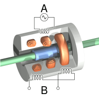
An LVDT is composed of seven components, not including the conditioning circuitry:
- Primary coil
- Secondary coil 1
- Secondary coil 2
- Ferromagnetic core
- Shaft
- Shield
- Handle
The ferromagnetic core is the moving component whose position within the shaft is sensed. Around the shaft are wound three inductors, the primary winding in the middle and the secondary windings (wound in opposite direction) on either side of the primary. Each of the secondaries should have the same number of turns and be of the same length, otherwise the null position and linearity will be affected. A cylindrical shield protects the windings from damage and also serves to contain the magnetic field used for sensing. The physical component which will be measured using the LVDT is mechanically coupled to the ferromagnetic core using a threaded (and non-ferromagnetic) handle. For some applications, a guide system and even a spring-return (which is known as a “gagehead” configuration) may be included in the assembly.
Signal Conditioning
The conditioning circuit for an LVDT is relatively complicated and plays an important part in the linearity and precision of the device (Nyce2004). Firstly, an oscillator excites the primary winding which is coupled with the secondary windings each to a degree dependent upon the position of the ferromagnetic core. If the core is in the centre position, then the secondaries will be equally coupled to the primary. If the core is displaced from its centre position, then one of the secondaries will be more strongly coupled and will echo the excitation signal to a greater degree.
One of the secondary windings, being wound in opposite direction to the other two inductors, will output the excitation signal in opposite phase. This is used in order to obtain a differential voltage indicating the direction of the displacement: the outputs of the secondary windings are rectified and summed to produce a voltage which varies linearly between the +/- the maximum displacement with the centre position being at zero volts.
Devices
| MSI Inc. / Shaevitz MHR-500 | |
|---|---|
| Sources | |
Component Distributors, Inc CAN$ 599.00
|
| Description | ±12.7mm AC-operated LVDT |
| Datasheet | MHR_Series.pdf |
| Resources | |
| Notes | |
| Variants |
| MSI Inc. / Shaevitz GCD-121-500 | |
|---|---|
| Sources | Digikey CAN$ 955.00 |
| Description | ±12.7mm DC-operated spring-return (gagehead) LVDT |
| Datasheet | GCD_Series.pdf |
| Resources | |
| Notes | |
| Variants | |
External links & references
- (Nyce2004) David S Nyce, “Linear Position Sensors”. John Wiley & Sons, Hoboken, New Jersey, 2004.
- (Webster1999) John G Webster, “The Measurement, Instrumentation, and Sensors Handbook”. CRC Press with IEEE press, Boca Raton, Florida, 1999.
- (Wilson2005) John S Wilson, “Sensor Technology Handbook”. Elsevier, Burlington, Massachusetts, 2005.
- (Hoadley1936) George B Hoadley, “Telemetric System”. US Patent Application #2196809, March 17th 1936 (Patented on April 9th 1940).
- (Powell2009) Mike Powell, Mike’s Flight Deck
- RDP Group, 2002, LVDT principle of operation.

