Table of Contents
LuSense CPS² 155
Summary
Introduction
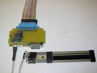
The LuSense CPS² 155, commonly referred to as an FSR 155, is manufactured by LuSense. CPS² stands for Co-ordinates & Pressure Sensitive Sensor. It is similar to a conventional force-sensitive resistor, except that it is additionally sensitive to position. Depending on the conditioning circuit used, the sensor can be configured to measure the amount or the location of the applied pressure. Only slight modifications are necessary to change the conditioning electronics from position sensing to pressure sensing. Thus the two circuits can be constructed together with the mode of operation controlled by a multiplexer, for virtual dual-output of pressure and position information. The multiplexer can be run at a very fast rate (1.5 kHz, for example), yet at discrete points in time the FSR 155 can only output either position or pressure. To compensate for this, the output segments of the respective circuits may be seperated, and followed with a simple sample-and-hold circuit. This allows the output of one circuit to retain the measure value while the other circuit is reading. The switching rate is set to a frequency which makes the hold time negligible. Consequently, the FSR 155 can be used to gather essentially simultaneous readings in position and pressure. For analysis purposes, we can think of the sensor and circuity as two independant subcircuits.
Physical Layout
The dual sensing capabilities of the FSR 155 derive from the layering of the piezoresistive substrate within the sensor. Each of the analysis subcircuits is a voltage divider. In order to understand the voltage they divide, it is important to understand the physical layout of the sensor.
The FSR 155 is comprised of three leads embedded into a force-sensitive variable-resistive strip:
- Supply lead – Provides and shields the input voltage, and makes it available at the opposite end of the sensor.
- Control lead – Connected to a piezoresistive strip that runs straight through the sensor and meets with the available voltage at the opposite end.
- Output lead – Woven along the length of the sensor, and is separated from the control strip by a layer of piezoresistive material.
The control and output leads appear to be “comb-shaped” and run densely interleaved in each other for the length of the sensor, occupying the total of its width.
Output
The mode of operation of the sensor is controlled by the connection of the control lead. As the dependent variable of the sensor is a variable resistance, the output measurement circuit can be a simple voltage divider. To create a voltage division circuit with pressure sensitive resistance, the control lead is left floating and the supply lead is tied to ground via a 47 kΩ resistor. To create a voltage division circuit with position sensitive resistance the control lead is tied to ground and the supply lead is left floating.
The change in circuitry that needs to take place to allow for one mode of operation or the other is minimal. The simplicity of the changes that need to occur allows one to use an electric switch to accomplish this task. A multiplexer is an electronic switch, and is the ideal IC component for this.
The control and output leads are thus connected to the multiplexer in order that the multiplexer may automatically control the path to ground. The output lead is also connected to another gate of the multiplexer that will distribute the output out of one gate in the case of position, and another in the case of pressure. These outputs are coupled to ground via capacitors to maintain voltage while the other output is active. The coupled voltage is then amplified to provide the appropriate scaling.
All multiplexers contain a set of switches, and a corresponding set of logical inputs that dictate the operation their respective switch (open or closed). Multiplexers are also capable of very high switching rates. In the circuit for this sensor, a 1.5 kHz oscillator used. The output of the oscillator is tied to all the control inputs, thus ensuring that all switches behave identically.
Devices
| LuSense CPS² 155 (FSR 155) | |
|---|---|
| Sources | Radiospares €32.52 |
| Description | Linear potentiometer, senses both pressure and position, sensing arera of 205 mm x 15 mm/ |
| Datasheet | |
| Resources | LuSense CPS² Product Page |
| Notes | Three pin device that needs a demultiplex circuit to obtain force and position signals independently (circuit available below (fsr155.wmf), curtesy of Patrice Pierrot). |
| Variants | CPS² 1642, with a sensing area of 65 mm x 15 mm. |
Media
References
LuSense, 2005, “CPS² Product Page” Luxembourg, Luxembourg

