Table of Contents
Temperature
Summary
Introduction
There are four main contact temperature-sensing devices available, divided in three families: thermocouples (self-generating sensors), resistance temperature detectors and thermistors (resistive sensors), and temperature-transducing ICs (PN or Semiconductive). These sensors translate the temperature into a reference voltage, resistance or current, which is then measured and processed and a numerical temperature value is computed.
Types of temperature sensor
Thermocouples
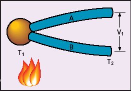
Thermocouples are a physically simple sensor, though how they function is more complex. Figure 1 shows the basic wiring of a thermocouple. A thermocouple is comprised of two dissimilar alloys (wires A and B) joined at one end, called the “hot junction” (T1). The other leads are connected to a voltmeter or other input device that measures the voltage (V1) across the '“cold junction” (T2).
The hot junction is the sensing element, and the cold junction is kept at a constant reference temperature. A voltage is produced as the hot junction is heated, which is proportional to the temperature difference between the two junctions. This principle, called the thermocouple effect was discovered by Thomas Seebeck in 1821 (Awtrey, 2001). And so, the electromotive force (EMF) produced when the junctions of dissimilar alloys are maintained at different temperatures is known as the Seebeck EMF.
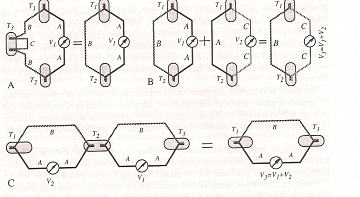
Fraden (1997) defines three laws for proper connection of thermoelectric materials :
Law No.1 (A) - A thermoelectric current can not be established in a homogeneous circuit by heat alone. (LAW OF HOMOGENEOUS CIRCUITS)
Law No.2 (B) - The algebraic sum of the thermoelectric forces in a circuit composed of any number and combination of dissimilar materials is zero if all junctions are at a uniform temperature. (LAW OF INTERMEDIATE METALS)
Law No.3 (C) - If two junctions at temperature T1 and T2 produce Seebeck voltage V2, and temperatures T2 and T3 produce voltage V1, then temperatures T1 and T3 will produce V3 = V1 + V2. (LAW OF INTERMEDIATE TEMPERATURES)
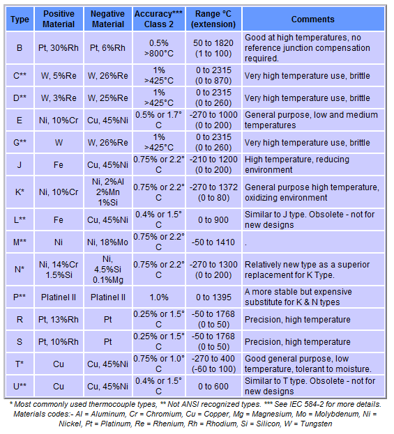
The theory behind the thermocouple and thermoelectric effect is based upon the atomic structure of the alloys and is beyond the scope of this report. The voltage is also dependant upon the type of conductors used. Different alloys produce distinct voltages; therefore standards have been established to facilitate reliability and repeatability. There exist eight standardized alloy combinations, each referenced by a letter: B, E, J, K, R, S, T, and N. The following table describes the main characteristics of these combinations (www.capgo.com)
The Seebeck EMF produced by a thermocouple is of such small scale that the voltage must be amplified and processed by a specialized thermocouple input module.
Thermocouples are calibrated with a cold junction temperature of 0°C. However, two problems arise when connecting thermocouples to their input device: firstly, the input terminals, which are constructed with a different type of metal, create their own Seebeck voltage which alters the actual thermocouple voltage; and second, the device has to be recalibrated for an operational cold junction temperature. With the advancements in technology over the past few decades, these input modules have been designed to be self-calibrating and self-compensating and are able to be configured for a variety of thermocouple types.
Resistance temperature detectors (RTDs)
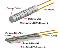
The same year Seebeck discovered the principle behind the thermocouple (1822), Humphrey Davy announced that the resistivity of metals were highly influenced by temperature. Two major types of RTDs are available for industrial and commercial use : wire-wound and thin film. (www.sensortips.com)
RTDs function on the principle that as the sensing element is heated, the resistance of the metal wire increases proportionally. RTDs are commonly made with copper, nickel, or nickel-iron, but platinum RTDs are the most linear, repeatable, and stable. The resistance is almost a linear function of temperature for very pure platinum, which is the primary reason for this metal’s pervasiveness in RTDs.
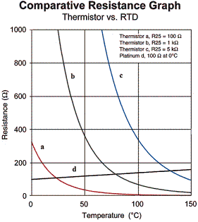
RTDs are calibrated to exhibit a resistance of 100 Ω at 0°C. Their resistance at other temperatures depends on the value of the mean slope of the metal’s resistance-temperature plot, known as the constant alpha. Alpha is dependant upon the platinum’s purity. Although RTDs are fairly linear, advanced RTD input devices use software with curve fitting and software processing to increase their accuracy at higher temperatures.
Thermistors
Thermistors, like RTDs, vary their resistance as the ambient temperature is changed. Unlike RTDs, which use pure metals, the material used in a thermistor is generally a ceramic or polymer. Positive temperature coefficient (PTC) thermistors will show an increase of resistance with increasing temperature, while negative temperature coefficient (NTC) thermistors will show a decrease of resistance with increasing of temperature. Thermistors typically achieve a higher precision than RTD within a limited temperature range (usually −90 °C to 130 °C). (www.sensorsmag.com)
Comprised of a metal oxide ceramic semiconductor sensing element, thermistors are notorious for their non-linearity, which engineers often dampen by implementing pairs of offsetting thermistors, providing a more linear output. These temperature dependent resistors are highly sensitive to temperature change. Thermistors vary their resistance about -4.4% at 25°C when heated by one degree Celsius (Ogden, 2000). Since thermistors are resistive devices, in operation an electrical current is passed through the sensor. Some of this electricity is converted into heat, which may cause slightly higher than ambient temperature readings. Thermistors can operate without significant error with long lead wires, because of their high base resistance. Thus they can be installed at long distances, upwards of one hundred metres, from the input module. Thermistor resistances are non-standardized and vary from 100 to 1,000,000 Ω at 25°C (Ogden, 2000).
Temperature-transducer ICs
Semiconductor temperature sensors are produced in the form of ICs. Their design results from the fact that semiconductor diodes have temperature-sensitive voltage vs. current characteristics. When two identical transistors are operated at a constant ratio of collector current densities, the difference in base-emitter voltages is directly proportional to the absolute temperature.
The use of IC temperature sensors is limited to applications where the temperature is within a –55° to 150°C range. The measurement range of IC temperature sensors may be small compared to that of thermocouples and RTDs, but they have several advantages: they are small, accurate, and inexpensive.
Temperature sensing ICs are available either in analog form, which output a voltage or current which is proportional to the temperature, or digital, which communicate temperature over a digital communication line, such as one-wire PWM, two-wire I2C, or a multiple wire SPI connection.
Projects That Use Temperature Sensors
The Sonic City project developed a wearable system that creates music based on data from sensors measuring bodily and environmental factors. This includes environmental temperature measurements. A video summarising the project is linked to in the media section below, and Viktoria site for the project has a more detailed description.
Sound Kitchen includes temperature sensors and uses voltage changes in liquids to create music. The liquids include wine, soda and other items you might find in a kitchen, and the over all aesthetic connects strongly with cooking.
Comparison of temperature sensor types
The following table offers a comparison of the different characteristics of the various temperature sensor types.
| Characteristic | Platinum RTD | Thermistor | Thermocouple | Temperature IC |
|---|---|---|---|---|
| Active Material | Platinum Wire | Metal Oxide Ceramic | Two Dissimilar Metals | Silicon Transistors |
| Changing Parameter | Resistance | Resistance | Voltage | Voltage or Current |
| Temperature Range | -200°C to 500°C | -40°C to 260°C | -270°C to 1750°C | -55°C to 150°C |
| Sensitivity | 2 mv/°C | 40 mV/°C | 0.05 mV/°C | ~1 mv/°C or ~1 uA/°C |
| Accuracy | -45 to 100°C: ±0.5°C; 100 to 500°C: ±1.5°C; 500 to 1200°C: ±3°C | -45 to 100°C: ±0.5°C; degrades rapidly over 100°C | 0 to 275°C: ±1.5 °C to ±4°C; 275 to 1260°C: ±0.5 to ±0.75% | ±2 °C |
| Linearity | Excellent | Logarithmic, Poor | Moderate | Excellent |
| Response Time | 2-5 s | 1-2 s | 2-5 s | |
| Stability | Excellent | Moderate | Poor | Excellent |
| Base Value | 100 Ω to 2 kΩ | 1 kΩ to 1 MΩ | < 10 mV | Various |
| Noise Susceptibility | Low | Low | High | High |
| Drift | +/- 0.01% for 5 years | +/- 0.2 to 0.5°F per year | 1 to 2°F per year | 0.1°C per month |
| Special Requirements | Lead Compensation | Linearization | Reference Junction | None |
| Device Cost | $60 - $215 | $10 - $350 | $20 - $235 | $5 - $50 |
| Relative System Cost | Moderate | Low to Moderate | Moderate | Low |
Devices
Media
External Links & References
- Hollinger, Avrum, 2002. Workterm Report - Temperature Sensors
- Awtrey, Dan (Dallas Semiconductor), 2001. The 1-Wire Thermocouple, Sensors Online.
- Ogden Manufacturing, 2000. Input Specifications, Technical Specifications Document.
- O'Keefe, Claire and Black, Brian (Analog Devices). Choosing an IC temperature sensor, Online Article, Wilmington MA.
- Omega Engineering, 1999. Practical Guidelines for Temperature Measurement, Online Technical Report.
- Thermocouple Types (Watlow)
- Lecture Series on Industrial Instrumentation by Prof.Alok Barua, Department of Electrical Engineering,IIT Kharagpur Lecture 7 - Thermistors, Lecture 8 - Thermocouples, Lecture 9 - Resistance Temperature Detector

