Table of Contents
Sound Pressure
Summary
Introduction
Sound pressure sensors, or microphones, as they are most commonly known, are a specific type of transducer that allows conversion from sound-related air pressure to electrical (or digital) signals. Although there are different types of microphones, such devices are usually composed of a transducer element, a diaphragm that converts sound pressure into mechanical energy, and an electronic circuit in order to adapt the output of the system. There are several different types of microphones, but the ones that are used the most are:
- The Dynamic Microphone
- The Condenser Microphone
- The Ribbon Microphone
These transducers are principally differentiated by the way they convert the produced mechanical energy resulting from sound pressure, into an electrical signal proportional to the received sound waves. In an ideal case, a microphone should only respond to sound pressure without regards towards the location of the sound source. However, as it will be later explained, these types of transducers do exhibit some type of directionality along their main axis because of short-wave diffraction effects.
The Dynamic Microphone
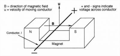
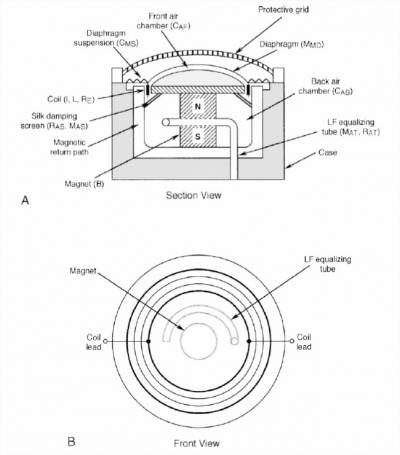
The dynamic pressure microphone is mainly based on the principle of magnetic induction. Because they possess a low-level output, it is necessary to increase the level of the resulting signal through some means of electrical amplification. These transducers are also known as electro dynamic, electromagnetic, or moving coil microphones. The basic working principle of such devices consists of a conductor (or wire) that moves back and forth along a magnetic field, thus generating a resulting output voltage proportional to the strength of the magnetic field in question:
e(t) = B l u(t)
Where e(t) is the instantaneous output voltage, B is the magnetic flux density, l is the length of the conductor and u(t) is the instantaneous velocity of the conductor.
Figure 1. Basic principle of magnetic induction (Rayburn, 2011).
Figure 2. Front and section views of a moving coil microphone assembly (Rayburn, 2011).
The most common uses for dynamic microphones usually consist of on-stage musical performances, because of their robustness and their lack of dependence on an external power source. This is also why these microphones are usually used to record any type of acoustical alteration with high dynamic levels.
The Condenser Microphone
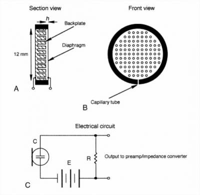
A condenser, or capacitor microphone, works under the physical principle of capacitance. Here, the condenser capsule consists of a thin membrane placed closed to a solid metal plate. This membrane (or diaphragm) must be constructed with an electrically conductive material in order for it to generate a voltage output when stimulated by incoming soundwaves that produce back-and-forth movements between this element and the solid metal plate. However, this system’s output signal current has a noticeably low level, so an external power source is necessary for it to work properly. This “impedance converter” allows for a higher signal current availability, thus resulting in a useful output signal. Generally, this external power source consists of a +48 V boost that is colloquially best known as “phantom power”. This type of microphone operates on the static relationship:
Q = C E
Where Q equals to the electrical charge (in coulombs) on the capacitor plates, C is the capacitance (in farads) and E is the applied dc voltage.
Figure 3. Relationships in a charged capacitor (Rayburn, 2011).
Figure 4. Simplified electrical circuit, plus front and section views of a condenser microphone assembly (Rayburn, 2011).
Condenser microphones are widely used in studio music recordings due to their superior sound quality and sensitivity towards incoming soundwaves. These microphones also have the best transient response and the widest frequency response of all types of microphones, while keeping a low noise level.
The Ribbon Microphone
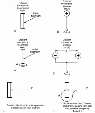
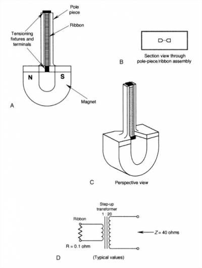
Ribbon, or pressure gradient microphones, are a variant of the dynamic pressure transducer type, because they follow the same principle of electromagnetic induction as a moving coil microphone. Here, sound pressure is sensed at two very close spaced points consisting of the front and back sides of the diaphragm. The difference is that instead of producing an electrical current by using a moving coil and a membrane, a ribbon transducer employs a narrow and extremely thin strip of aluminum foil. Inside this setup, the membrane itself will be the electrical conductor that moves inside the magnetic field. As with the capacitor, the ribbon transducer allows for increased recording accuracy. However, because of the conductive nature of this setup, the produced output level will be much lower. Therefore, ribbon microphones need to implement a step-up transformer in order to multiply the transducer’s output voltage. In addition, these microphones also possess low sensitivity, resulting in the need for a low-noise preamplifier with great amounts of gain. The ribbon’s electrical output will be given by:
E ejωt = B l U ejωt
Where E is the rms output voltage of the microphone, B is the flux density in the magnetic gap (tesla), l is the length of the moving conductor in the magnetic field (m), and U is the rms velocity of the conductor (m/s).
Figure 5. Definition of the pressure gradient (Rayburn, 2011).
Figure 6. Typical electrical circuit, plus front and section views of a ribbon gradient microphone assembly (Rayburn, 2011).
Ribbon microphones are very fragile and can be damaged easily. Therefore, they are almost limited to in-studio controlled applications where treble response is not an essential requirement.
Polar Patterns
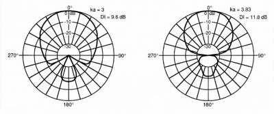
The polar pattern of a microphone is used to define the device’s inherent directionality, thus describing the angle-based sensitivity of the transducer. In a typical polar pattern diagram (as shown below), 0 and 180 degrees represent the front and back ends of the microphone diaphragm, while the left and right edges are respectively represented by 270 and 90 degrees. Each one of the described circumferences represent a specific amount of dB reduction in audio sensitivity, starting from the outermost circle towards the center:
Figure 7. Theorical polar response (RØDE Microphones, 2015).
The most common polar patterns include:
- The cardioid polar pattern. The cardioid polar pattern is the most common of the directional polar patterns. Its name originates from its polar shape characteristics that resemble a heart. Furthermore, we can find the hyper-cardioid and super cardioid which are variants of the original polar pattern. The difference between these polar patterns consists in the level of directionality at the front of diaphragm. Hyper and super-cardioids possess a narrower sensitivity at the front, with reduced levels at the sides, and additional rear directionality.
- The bidirectional polar pattern. This polar pattern is also known as a figure-of-eight directionality pattern. As their name states, such devices are capable of registering sound coming from both ends of the diaphragm. The microphones described by this type of pattern can produce highly realistic sound duplication because of their ability to record more of the natural ambience of the recording space.
- The omnidirectional polar pattern. The omnidirectional polar patterns are able to record sound incoming from all sides in a perfect sphere. This results in increased movement freedom as the angle position of the source will not affect the overall sound of the recording.
Frequency Response
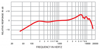
The frequency response of a microphone, as its name states, describes the frequency range of sound that a microphone can correctly reproduce. The signature sound of such devices is mostly defined by their frequency response, which is typically represented by a graphical response curve. The two main types of frequency responses are:
- The flat response. This type of response has an equal sensitivity throughout the frequency range, thus resulting in a straight-lined response curve. The flat response has the advantage of reproducing sounds with increased accuracy.
- The shaped response. This type of frequency response has variable sensitivity within the capture range. Usually, microphones with a shaped response, are less sensitive to low frequencies, thus reducing noise level at this range. Furthermore, they will also typically boost the upper mid-range frequencies (3 kHz – 6 kHz).
Figure 8. Frequency response curve (Rochman, 2017).
Media
A video from Soundfly briefly explaining the contents of this page
Devices
| Company | Neumann |
|---|---|
| Model | KM 184 |
| Sources | Neumann Official Website US$ 999.00 |
| Description | Small diaphragm condenser microphone |
| Datasheet | Specs |
| Company | Shure |
|---|---|
| Model | SM7B |
| Sources | Shure Official Website US$ 399.00 |
| Description | Cardioid dynamic microphone |
| Datasheet | Specs |
| Company | RØDE Microphones |
|---|---|
| Model | NTR |
| Sources | RØDE Microphones Official Website US$ 999.00 |
| Description | Active ribbon microphone |
| Datasheet | Specs |
External Links & References
- A Quick Guide to Microphones. (2016, December 9). [Video]. YouTube. https://www.youtube.com/watch?v=PE6Qn4ZiEyo
- Made How. (n.d.). How microphones are made - material, history, used, parts, industry, machine, History, Raw Materials, Design. How Products Are Made. http://www.madehow.com/Volume-7/Microphone.html
- Mantione, P. (2020, May 12). A Basic Guide to Microphone Specifications. Pro Audio Files. https://theproaudiofiles.com/mic-specs/
- Neumann. (n.d.-a). Microphone Basics: What’s a Condenser Microphone? Neumann Official Website. https://www.neumann.com/homestudio/en/what-is-a-condenser-microphone
- Neumann. (n.d.-b). Microphone Basics: What’s a Dynamic Microphone? Neumann Official Website. https://www.neumann.com/homestudio/en/what-is-a-dynamic-microphone
- Rayburn, R. A. (2011). Eargle’s The Microphone Book, Third Edition: From Mono to Stereo to Surround - A Guide to Microphone Design and Application (Audio Engineering Society Presents) (3rd ed.) [E-book]. Focal Press. https://doi.org/10.4324/9780240820781
- Rochman, D. (2017). Mic Basics: What is Frequency Response? Shure. https://www.shure.com/en-US/performance-production/louder/mic-basics-frequency-response#:%7E:text=The%20frequency%20response%20is%20the,of%20a%20frequency%20response%20chart.
- RØDE Microphones. (2015, October 2). What are a microphone’s polar patterns? http://www.rode.com/blog/all/what-are-a-microphones-polar-patterns
- Shapton, D. (2004). Digital Microphones: A New Approach? Sound On Sound. https://www.soundonsound.com/techniques/digital-microphones-new-approach
- Wikipedia contributors. (2021, March 18). Microphone. Wikipedia. https://en.wikipedia.org/wiki/Microphone#Components

