Table of Contents
Basic Sensor Interfacing Techniques
Introduction
Interfacing computer systems to the outside world is an important issue in a large number of computer-related disciplines, from human computer interaction, to robotics, to interactive multimedia, to computer music. In order to do this, the computer systems require some form of sensors.
This report offers an introduction to the area of sensors for interactive computer systems. It covers the theory of a number of forms of sensors, and discusses how to interface them to a computer system.
Sensor Types
The majority of common sensors can be classified into two groups, based on their principal of electrical operation. These groups are:
- Resistive sensors
- Voltage-producing sensors
Resistive Sensors
Resistive sensors are sensors which act as variable resistors. Different input to the sensor causes it to change it's resistance. Each sensor generally has a nominal resistance, which is it's resistance value for zero input. It also offers a resistance range, with a minimum and maximum resistance value, representing the resistance at minimum and maximum input. These values are generally available from the manufacturer's datasheet, and are essential to the design of an interface circuit for the sensor.
Voltage-producing Sensors
Voltage-producing sensors produce a varying voltage dependant on their input. The range of voltage varies from sensor to sensor, and again, the information about the voltage range is available in the manufacturer's datasheet. As with the resistive sensors, it is the maximum and minimum values which are required to design an interface circuit for these sensors.
Signal Conditioning Circuits and Interface Devices
In order to get information from a sensor into a computer, the signal from the sensor must first be sent to an interface device of some form and from there to the computer. However, in order to be useful to the interface device, the signal from the sensor must often undergo some form of conditioning. Almost all interface devices designed to allow interfacing of sensors to computers are designed to accept a voltage signal in the range of 0 to 5 volts and to digitize this.
This means that the aim of the signal conditioning circuit is to take whatever output is available from the sensor, whether voltage or resistance, and convert it to a 0 to 5 volt signal. This process generally involves a combination of one or more simple processes: converting a resistance to a voltage, dividing a voltage, amplifying a voltage and shifting a voltage.
Signal conditioning methods
Converting a resistance to a voltage
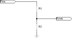
The process of converting a resistance to a voltage involves the use of a circuit known as a voltage divider. A voltage divider uses two resistors in series to divide the input voltage by the ratio of the resistances. This is shown in Figure 1. The division of the voltage is according to the following formula:
If one of the resistors in the circuit is replaced with a variable resistance, then the output voltage is proportional to the change in resistance of the variable resistor. As a resistive sensor operates as a variable resistor, the resistive sensor can be used to replace one of the resistors, giving a voltage output which is proportional to the resistance of the sensor.
The most suitable value for the other resistor in the circuit can be determined using the voltage divider equation, the minimum and maximum resistance values for the sensor and the input voltage (commonly 5V).
In order to attain a minimum output voltage (say 0.01V) when the sensor is at its minimum resistance, the value of the other resistor is determined as follows:
This simplifies to:
This resistance can then be used along with the maximum resistance of the sensor to determine the maximum output voltage for the circuit as follows:
The circuit is now acting as a voltage-producing sensor with a range of 0.01 to Vmax volts.
Thisonline resistor calculator utility should help you decide which is the best fixed resistor for your application.
Dividing a voltage
As stated in the last section, the voltage divider circuit reduces the input voltage based on the ratio of the resistors in the circuit. It is often the case where a sensor will produce an output voltage which is outside the range of voltages which can be read by an analog-to-digital converter. In this case it is possible to use a voltage divider to reduce the voltage. For instance if a sensor produces a voltage in the range of 0 to 40V and the analog-to-digital converter requires a voltage in the range of 0 to 5V, we need only pass the voltage through a voltage divider as shown in Figure 1 where the resistor values are determined to give the ratio of 5/40:
This can be simplified to:
Any values of resistors R1 and R2 can be used, so long as they give the required ratio (in this example, so long as R1 is 7 times R2).
Amplifying a voltage
Sometimes a sensor will produce a small output voltage, perhaps with only a few mV of range. In this case it is necessary to amplify the voltage so that it covers as much of the range of the analog-to-digital converter as possible.
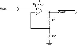
The easiest way to achieve this amplification is to use an Opamp (Operational Amplifier). Figure 2 shows the circuit required to use an opamp chip as a voltage amplifier. This circuit amplifies the voltage by a factor which is determined by the ratio of the resistors as follows:
So, to determine the required resistors for a particular amplification you can use the following formula:
This can then be simplified to the following:
So, for example, for an amplification of 20 times, R2 must be 19 times R1.
Shifting Voltages
Sensors also exist which produce a voltage output which is symmetrical around 0V. This means that they produce a -X to +X volt output. As analog-to-digital converters generally require a positive voltage, it is necessary to shift these voltages upwards so that they operate from 0 to 2X volts.
The circuit for shifting a voltage upwards is more complex than the previous circuit. It uses a dual opamp to add a fixed voltage to the input signal. The voltage to be added is determined by the values of two resistors R1 and R2 in a voltage divider. Figure 3 shows this circuit.
The amount by which the voltage is shifted is determined by the voltage divider. To determine the values of the voltage divider resistors, use the voltage divider formula, along with the supply voltage (Vs) and the voltage you want to add to the input signal (Va).
Combining signal conditioning circuits
It is also possible to combine these circuits in cases where using only one will not give you the required change in the signal. So, for instance, if you have a sensor which produces a -20V to +20V signal, you could condition the signal to give 0 to 5V by shifting the voltage by 20V, giving a range of 0V to 40V and then dividing the voltage by 8 using a voltage divider.
It is important to remember though that each conditioning step will introduce some impurities in the signal. This means that the more steps the signal goes through the less pure the signal will be. Also, signals which go through extreme changes will exhibit more impurities than signals which are only slightly changes. That is, amplifying a signal by a factor of 1000 will introduce greater impurities than amplifying it by a factor of 2.
Summary
This document provided an introduction to basic sensor interfacing circuits, introducing the two major classes of sensor and providing methods of conditioning the signals from the sensors to provide a useful voltage range for analog-to-digital conversion.


